
What
exactly is an OPerational AMPlifier? Let's define what that
component is and look at the parameters of this amazing device. An operational
amplifier IC is a solid-state integrated circuit that uses external feedback to
control its functions. It is one of the most versatile devices in all of
electronics.
The term 'op-amp' was originally used to describe a chain of high performance dc
amplifiers that was used as a basis for the analog type computers of long ago.
The very high gain op-amp IC's our days uses external feedback networks to
control responses. The op-amp without any external devices is called 'open-loop'
mode, refering actually to the so-called 'ideal' operational amplifier with
infinite open-loop gain, input resistance, bandwidth and a zero output
resistance. However, in practice no op-amp can meet these ideal characteristics.
And as you will see, a little later on, there is no such thing as an ideal
op-amp. Since the LM741/NE741/µA741 Op-Amps are the most popular one, this
tutorial is direct associated with this particular type. Nowadays the 741 is a
frequency compensated device and although still widely used, the Bi-polar types
are low-noise and replacing the old-style op-amps.
Let's
go back in time a bit and see how this device was developed. The term
"operational amplifier" goes all the way back to about 1943 where this name was
mentioned in a paper written by John R. Ragazzinni with the title "Analysis of
Problems in Dynamics" and also covered the work of technical aid George A.
Philbrick. The paper, which was defined to the work of the U.S. National Defense
Research Council (1940), was published by the IRE in May 1947 and is considered
a classic in electronics. It was around 1947 that the Operational Amplifier
concepts were originally advanced. The very first series of modular solid-state
op-amps were introduced by Burr-Brown Research Corporation and G.A. Philbrick
Researches Inc. in 1962. The op-amp has been a workhorse of linear systems ever
since.
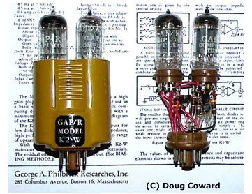 At
the left you see a picture of a K2-W tubes general purpose computing Op-Amp from
George A. Philbrick Researches. This type was first introduced in 1952, more
than a decade before the first transistorized version. The op-amp is shown with
and without its bakelite shell. What a beauty! The first solid-state monolithic
op-amp, designed by Bob Widlar, offered to the public in 1963 was the µA702
manufactured by
Fairchild Semiconductors but it had very weird supply voltages such as +12
and -6 volts and had a tendency to burn out when it was temporarily shorted.
Despite all these little shortcomings this device was the best in its day. It
contained just nine transistors and sold for about $300.00 US which limited the
sales to the Military and Aerospace consumers.
At
the left you see a picture of a K2-W tubes general purpose computing Op-Amp from
George A. Philbrick Researches. This type was first introduced in 1952, more
than a decade before the first transistorized version. The op-amp is shown with
and without its bakelite shell. What a beauty! The first solid-state monolithic
op-amp, designed by Bob Widlar, offered to the public in 1963 was the µA702
manufactured by
Fairchild Semiconductors but it had very weird supply voltages such as +12
and -6 volts and had a tendency to burn out when it was temporarily shorted.
Despite all these little shortcomings this device was the best in its day. It
contained just nine transistors and sold for about $300.00 US which limited the
sales to the Military and Aerospace consumers.
In 1965 the next major change was introduced in op-amp design by Bob Widlar with
the µA709 from Fairchild Semiconductor. It had higher gain, a larger bandwidth,
lower input current, and a more user-friendly supply voltage requirement of
approximately +/- 15 Volt DC. The tremendous success of the 709 was associated
with high production demands causing rapid and steep price reductions. This
particular op-amp, introduced at about $70, was the first to break the $10
barrier and again not much later the $5 barrier. By 1969, op-amps were selling
for around $2.
The outrageous success of the µA709 emboldened Bob Widlar to request a
significant enhancement in his compensation. When his request was denied by his
boss, Charles Sporck, Widlar left Fairchild in 1966 to join the young National
Semiconductor. Ironically, one year later, Sporck became president of National
Semiconductors and so again becoming Widlar's boss. However, this time Sporck
had to accept Widlar's compensation package, which allowed Bob Widlar to retire
in 1970 just before his 30th birthday. Widlar worked briefly in 1980 for Linear
Technology and continued to produce designs for National Semiconductors on a
consulting basis for the rest of his life.
Under the brilliant guidance and futuristic view again of Bob Widlar,
National Semiconductor decided to jump on the bandwagen with the release of
a more versatile op-amp version in the form of the LM101 in 1967. It had a an
increased gain (up to 160K) and operation range. One of the nicest features of
the LM101 was 'short-circuit' protection, and simplified frequency compensation.
This was accomplished by placing an external capacitor across selected
connection pins. The first op-amp to provide this internally was the hybrid
LH101, which was basically a LM101 with a capacitor in a single package.
But Fairchild was not done yet. It introduced in May 1968 an internally
compensated op-amp called the µA741. However, the differences between their
LM101 and the µA741 were very slight. Frequency compensation is accomplished
using an 'on-chip' capacitor. Offset null is accomplished by adjustment of
currents in input stage emitters. On the LM101, Offset is achieved by adjusting
current in input stage collectors.
In December 1968, an improved version of the LM101, the LM101A, was devised.
This device provided better input control over the temperature and lower Offset
currents.
National Semiconductor introduced the LM107, which had the frequency
compensation capacitor built into the silicon chip. The LM107 came out at the
same time as the LM101A.
In 1968, Fairchild Semiconductor issued the µA748. The device had essentially
the same performance characteristics as the µA741. The difference was external
frequency compensation.